Projects
1.STAR CCM+ Basics
A Flow analysis was done on NACA 0012 and NACA 4412 Airfoil at the 15 Degree angle of Attack with the Turbulent flow at the velocity of 50 m/s. The Values of Aerodynamic Forces were obtained in the form of Coefficeint of Lift and Drag.

2. Heat Exchanger Analysis
-
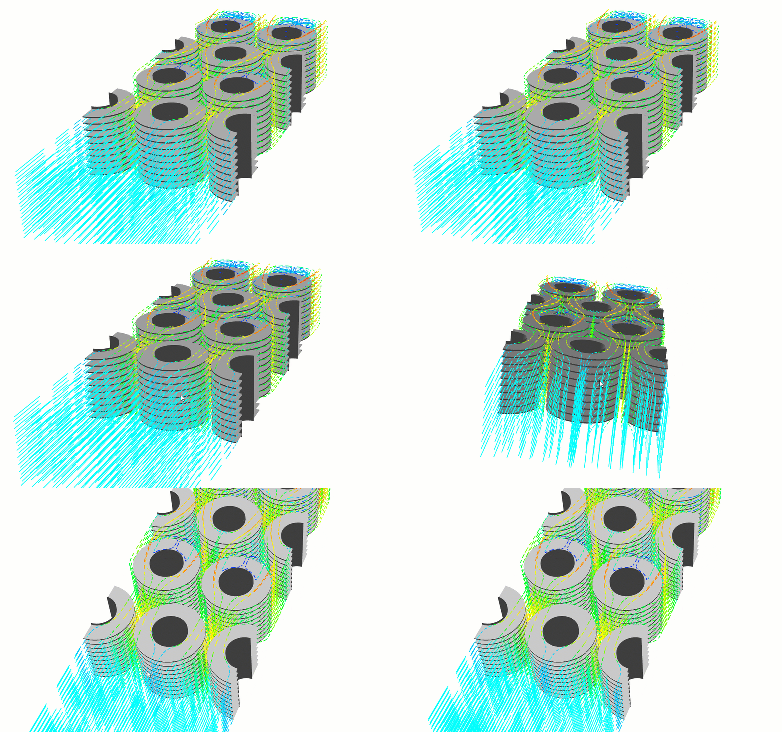
Heat Transfer Using Turbulator
Heat transfer analysis was done using Ansys Fluent.
All Project Data courtesy of Ansys Courses.

Heat transfer associated with forced convection over a thin flat plate with and without vortex generators in uniform laminar stream flow is analysed numerically in Ansys fluent. The vortex generators used where of type Rectangular, Triangular, Delta and curved Delta winglet type vortex generator. The analysis facilitates the curved delta type vortex generators provide higher heat transfer at velocity of 15m/s compared to triangular type vortex generator and rectangular type vortex generator. A trend to be seen that as velocity increases the heat transfer increases as there to be seen significant improvements in parameters like Drag coefficient, skin friction coefficient, heat transfer coefficient, Nusselt number and Stanton number. Total heat dissipation was found higher in curved delta and plane delta compared to triangular which is higher than rectangular type vortex generator.

Supersonic flow over a diamond-shaped airfoil is one of the classic canonical cases for demonstrating the application of shock-expansion theory. As the supersonic flow moves over the airfoil, it encounters both oblique shock waves and expansion waves. Though the flow-field is quite complicated, the shock-expansion theory is able to correctly estimate the flow variables such as pressure, Mach number, etc., in different regions of the flow.

Although the steady state approach is the cheaper and often preferred way to do CFD analysis, there are many applications where you must model the unsteady flow behavior. Performing a transient calculation is like performing a steady state calculation with some additional considerations. CFD problem of air flowing around a square cylinder is solved
High lift devices such as slats and flats are used on large commercial aircraft to generate a larger lift force. Slats are aerodynamic structures at the leading edge of the wing and flaps are deployed at the trailing edge. By controlling the distance between these structures and the main airfoil as well as their orientation, commercial aircraft are able to generate more lift at reduced airspeeds during take-off and landing, thus requiring shorter runways. Furthermore, the deployment of these elements also increases the drag force, which is incidental but helpful in slowing the aircraft down during its landing approach. When the aircraft is at cruise altitude, the slats and flaps are retracted into the wing. In this simulation example, we will understand the impact of flaps and slats on lift and drag forces. The 2D, three-element airfoil configuration comprises a fully deployed slat, main airfoil and flap.